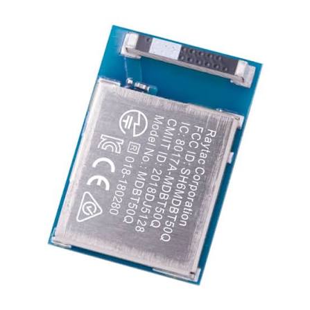
If you are designing a custom embedded system and trying to establish UART communication between a Raytac MDBT50Q-1MV2 BLE module (based on the Nordic nRF52840) and a host MCU like the STM32F405RGT6, you might run into a frustrating issue: completely silent serial lines.
Even with perfectly matched logic levels and correct TX/RX cross-wiring, the default PlatformIO framework configuration can prevent your data from transmitting. The root cause usually boils down to unmapped hardware pins and object conflicts within the Adafruit nRF52 Arduino core.
Here is a step-by-step guide on how to patch your PlatformIO environment and correctly configure your firmware to get UART up and running.
Step 1: Patch the PlatformIO Variant File
By default, the PlatformIO board variant file for the Raytac MDBT50Q-RX does not map the hardware pins for UART (P0.06 for TX and P0.08 for RX) to usable Arduino digital pins. You must manually extend the pin mapping array.
Your updated array should look like this:
const uint32_t g_ADigitalPinMap[] =
{
  45,  // D0  is P1.13 (LED1)
  43,  // D1  is P1.11 (LED2)
  15,  // D2  is P0.15 (Button)
  255, // D3  unused
  255, // D4  unused
  255, // D5  unused
  6,   // D6  is P0.06 (UART TX)
  255, // D7  unused
  8,   // D8  is P0.08 (UART RX)
};
Step 2: Avoid Redefining the Serial1 Object
A common mistake when writing the application code is attempting to manually declare the Serial1 object in main.cpp.
The Adafruit nRF52 framework already defines Serial1 internally within the Uart.cpp source file. Declaring it again will cause a multiple definition error or break the underlying EasyDMA routing.
Instead of declaring a new object, you simply need to interact with the pre-existing one.
Step 3: Correctly Initialize UART in Firmware
Because you are bypassing the default pin definitions, you must explicitly tell the Serial1 object which pins to use before starting the interface.
In your setup() function, use the setPins() method followed by begin():
#include <Arduino.h>

void setup() {
  // 1. Map the hardware pins explicitly (TX = P0.06, RX = P0.08)
  Serial1.setPins(6, 8);

  // 2. Initialize the serial port at your desired baud rate (e.g., 115200)
  // The default config is SERIAL_8N1 with no hardware flow control
  Serial1.begin(115200);

  // Wait for serial port to connect
  while (!Serial1) {
    delay(10);
  }

  Serial1.println("UART Initialized Successfully!");
}

void loop() {
  // Your serial handling logic here
}
Step 4: Verify Your Hardware Connections
With the firmware and framework correctly configured, double-check your physical wiring. Remember that UART requires a cross-connection:
- MDBT50Q TX (P0.06) connects to STM32 RX
- MDBT50Q RX (P0.08) connects to STM32 TX
- Ensure both microcontrollers share a common GND reference.
Once flashed, your MDBT50Q module will seamlessly stream serial data to your STM32 or any standard CH340 USB-to-UART bridge.